


Views: 0 Author: Site Editor Publish Time: 2026-09-23 Origin: Site


As semiconductor manufacturing advances to sub-5nm nodes, the tolerance for particle contamination in plasma etching chambers approaches zero. Legacy protective coatings are rapidly becoming obsolete in these critical zones. High-density halogen plasmas, specifically fluorine and chlorine-based chemistries, aggressively erode standard chamber components. This continuous erosion generates particulate defects, forces frequent maintenance downtime, and directly impacts wafer yield. To mitigate these material failures, materials scientists and equipment engineers are transitioning from traditional oxides to advanced halogen-resistant materials. Yttrium Oxyfluoride (YOF) has emerged as a primary candidate for critical zone protection. It offers unmatched chemical stability and structural integrity under extreme reactive ion etching conditions.
Superior Halogen Resistance: Yttrium Oxyfluoride demonstrates exceptional chemical stability in both fluorine and chlorine-based plasma environments compared to legacy alumina (Al2O3) and yttria (Y2O3) coatings.
Microstructural Advantage: The nanocrystalline structure of YOF reduces grain boundary diffusion pathways, significantly suppressing the penetration of corrosive species and subsequent particle generation.
Deposition Flexibility: YOF can be applied via multiple methods—including thermal spray, aerosol deposition (AD), and suspension spray—allowing engineers to balance coating density, thickness, and cost based on component geometry.
Yield-Driven ROI: While the initial material and application costs of YOF are higher than traditional ceramics, the investment is offset by extended mean time between cleaning (MTBC) and reduced wafer scrap.
Aluminum Oxide (Al2O3) served as the industry standard for chamber protection for decades. However, its performance degrades rapidly under modern fluorine plasma exposure. When exposed to gases like CF4 or SF6, fluorine radicals react with the alumina surface to form aluminum fluorides (AlF3). These byproducts possess a high vapor pressure at standard etch operating temperatures. They sublimate under vacuum conditions, stripping away the protective layer and releasing aluminum-containing particulates directly into the process chamber. While Al2O3 remains useful for remote, non-critical chamber zones due to its accessibility, it cannot survive direct high-density plasma bombardment near the wafer.
Pure Yttrium Oxide (Y2O3) was introduced to solve the aluminum contamination issue. It performs well in many environments but exhibits severe limitations in highly aggressive chlorine and fluorine plasmas. When Y2O3 is exposed to fluorine, it undergoes a chemical conversion to Yttrium Fluoride (YF3). This in-situ fluorination causes a massive volume expansion within the crystal lattice because the molar volume of YF3 is significantly larger than that of Y2O3. The expansion induces severe compressive stress, leading to mud-flat cracking, blistering, and eventual coating spallation. These micro-cracks become active generation sites for killer defects on the wafer.
Chamber component degradation severely impacts manufacturing efficiency. Degraded coatings require frequent tool teardowns for part replacement. This maintenance downtime halts production lines and requires extensive requalification procedures. Furthermore, undetected micro-flaking introduces microscopic contaminants that destroy sub-5nm transistor structures, leading to massive yield losses that far outweigh the cost of the chamber components themselves.
Modern plasma-resistant coatings must meet strict technical requirements to survive in high-volume manufacturing (HVM) environments. Engineers evaluate new materials against a rigid set of performance metrics.
Near-Zero Porosity: Any surface voids or interconnected pores allow reactive gases to penetrate and undercut the coating, attacking the underlying aluminum substrate.
High Adhesion Strength: The protective layer must not shear off under mechanical or thermal stress. Thermal spray coatings typically require bond strengths exceeding 30 MPa.
Chemical Inertness: The material must resist chemical conversion when bombarded by both fluorine and chlorine radicals, preventing the formation of volatile byproducts.
Matched Coefficient of Thermal Expansion (CTE): Plasma chambers undergo aggressive cyclical heating and cooling. The coating must possess a CTE that closely matches the underlying substrate to prevent shear stresses and premature delamination.
Phase Stability: The material must maintain its crystalline structure without undergoing destructive phase transformations during prolonged RF exposure.
HVM establishes rigid baselines for acceptable particle generation rates. Coatings must generate near-zero particles larger than a few nanometers over thousands of RF hours. Even a slight increase in particulate counts triggers immediate tool interlocks, forcing unscheduled maintenance.
Yttrium Oxyfluoride exhibits profound thermodynamic stability under reactive ion etching (RIE) conditions. Its structural resilience stems from its unique mixed-anion composition. The matrix already contains highly stable Y-F and Y-O bonds. Because fluorine is already integrated into the crystal lattice, the material resists further fluorination when bombarded by fluorine plasmas. The activation energy required to displace the existing oxygen atoms or break the Y-F bonds is exceptionally high.
This pre-existing fluorination prevents the volume expansion seen in pure Y2O3. The lattice does not need to expand to accommodate new fluorine atoms. The surface remains dimensionally stable. It effectively blocks the formation of volatile byproducts that plague alumina coatings, ensuring the coating thickness remains consistent over the component's lifespan.
Empirical evidence also demonstrates exceptional resistance to chlorine-based plasmas. Tuning the stoichiometric ratios of the material optimizes this resistance. For example, YOF 6% compositions show remarkable durability against chlorine radical attack. The specific ratio of oxygen to fluorine dictates the surface binding energy, preventing chlorine ions from displacing the existing lattice atoms and forming volatile yttrium chlorides.
The microstructure of YOF coatings heavily influences their protective capabilities. Advanced deposition techniques yield nanocrystalline formations, typically with grain sizes well under 100 nanometers. These ultra-fine grain structures fundamentally alter how corrosive species interact with the material surface.
Grain boundary diffusion is the primary mechanism by which plasma gases penetrate ceramic coatings. Gases travel along the high-energy boundaries between individual crystal grains. YOF's specific lattice structure, combined with its nanocrystalline morphology, creates highly tortuous and restricted diffusion pathways. The diffusion length increases exponentially, meaning corrosive ions cannot easily navigate these tight boundaries to reach the substrate.
Restricting these pathways suppresses subsurface corrosion. If gases cannot penetrate the surface, they cannot react with the underlying aluminum or ceramic substrate. This mechanism prevents plasma undercutting. Consequently, it eliminates the primary cause of coating delamination and subsequent particle contamination in the process chamber.
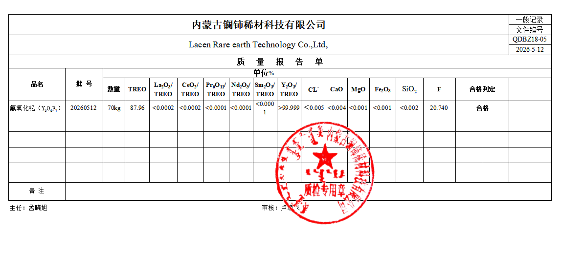
Applying thermal spray grade yttrium oxyfluoride is the standard approach for coating large-area members of semiconductor production apparatuses. Chamber walls, large liners, and exhaust baffles require thick, durable protective layers. Thermal spray efficiently covers these expansive surface areas with high deposition rates.
Atmospheric plasma spray (APS) is the most common thermal method. It utilizes an argon/hydrogen or argon/helium plasma jet to melt the powder and accelerate it toward the substrate. However, APS comes with distinct trade-offs. The rapid cooling of splattered particles creates a lamellar structure that inherently contains microscopic voids and splat boundaries. APS coatings typically exhibit higher porosity levels (1-5%) and greater surface roughness compared to vacuum methods.
To mitigate these issues, post-deposition treatments are mandatory. Engineers utilize specialized polymer sealing techniques or thermal annealing to close micro-pores in thermal sprayed YOF. Sealing these voids prevents plasma gases from penetrating the coating and attacking the aluminum substrate beneath. Laser glazing is also emerging as a technique to melt the top few microns of the coating, creating a fully dense, glass-like surface layer.
Aerosol Deposition (AD) offers a radically different approach for applying yttrium oxyfluoride coating powder. This solid-state deposition method aerosolizes the powder in a carrier gas and accelerates it through a de Laval nozzle into a vacuum chamber. The particles impact the substrate at supersonic speeds at room temperature. The kinetic energy of the impact causes room-temperature impact consolidation, fracturing the particles and fusing them into incredibly dense, nanocrystalline coatings without any thermal degradation.
AD-YOF coatings excel at suppressing particle contamination. The lack of thermal stress during deposition prevents micro-cracking and eliminates the CTE mismatch issues inherent to thermal spray. The resulting layer is nearly void-free, often achieving greater than 99% theoretical density.
Suspension plasma spray (SPS) utilizes a liquid carrier (such as ethanol or water) to inject sub-micron or nanoscale powders directly into the plasma plume. SPS achieves ultra-fine, nanostructured YOF layers on complex geometries. It bridges the gap between traditional APS and vacuum methods, yielding finer splats and lower porosity than standard APS while maintaining higher throughput than AD.
Selecting the correct deposition method requires a strict decision framework based on the specific chamber component. Component function dictates which metric takes priority.
Deposition Method | Typical Porosity | Adhesion Strength | Deposition Rate | Best Suited For |
|---|---|---|---|---|
Atmospheric Plasma Spray (APS) | 1% - 5% | Moderate (>30 MPa) | High | Chamber walls, large liners, exhaust baffles |
Suspension Plasma Spray (SPS) | 0.5% - 2% | High (>40 MPa) | Moderate | Focus rings, complex geometry liners |
Aerosol Deposition (AD) | < 0.1% | Very High (>50 MPa) | Low | Electrostatic chucks (ESC), showerheads |
Electrostatic chucks and showerheads feature complex geometries and demand absolute zero-porosity to prevent electrical arcing and gas flow disruption. These components require AD or SPS methods. Chamber walls, which endure less direct ion bombardment but require massive surface coverage, are better suited for APS due to the higher throughput.
Comparing fluorination resistance highlights the critical differences between YOF and Y2O3. Pure yttria reacts with fluorine plasmas to form YF3. This chemical conversion forces a massive volume expansion within the coating. The expansion causes the coating to blister and flake off, generating severe particle defects that land directly on the wafer.
YOF already contains fluorine. It does not undergo this destructive phase change. While Y2O3 offers a significantly lower risk of aluminum contamination than Al2O3, it falls short of YOF's stability in critical, high-density plasma zones. YOF provides the necessary structural stability that pure yttria lacks, maintaining its original volume and surface morphology even after thousands of RF hours.
Pure Yttrium Fluoride (YF3) offers excellent chemical resistance but suffers from poor mechanical properties. Pure fluorides are inherently brittle due to their strict ionic bonding. They are highly susceptible to mechanical damage during chamber assembly and thermal shock during plasma cycling. Cleavage occurs easily under mechanical stress.
YOF solves this brittleness. The oxygen content within the YOF matrix provides superior mechanical toughness. The mixed ionic-covalent bonds offer slight structural flexibility, drastically improving adhesion strength and fracture toughness compared to pure YF3. While other rare earth fluoride materials exist, they are generally relegated to specialized niche applications. YOF maintains broader utility across varied plasma chemistries due to this balance of chemical inertness and mechanical durability.
Material | Fluorine Plasma Resistance | Chlorine Plasma Resistance | Mechanical Toughness | Volume Expansion Risk |
|---|---|---|---|---|
Al2O3 | Low (Forms volatile gases) | Moderate | High | Low |
Y2O3 | Moderate (Converts to YF3) | Low (Micro-cracking) | Moderate | High |
YF3 | High | High | Low (Highly Brittle) | None |
YOF | Very High | Very High | High | None |
Deploying advanced coatings requires a strategic, tiered approach. Yttrium Oxyfluoride is not necessary for every square inch of an etch chamber. Engineers utilize legacy Al2O3 for non-critical zones located far from the plasma source, such as remote exhaust manifolds. Y2O3 is deployed in intermediate areas where plasma density is moderate and direct ion bombardment is minimal.
Premium YOF coatings are reserved strictly for high-density plasma critical zones. These include focus rings, showerheads, electrostatic chucks, and inner chamber liners directly exposed to radical bombardment. This targeted application extends the Mean Time Between Replacements (MTBR) for the most vulnerable components. Extending component lifespans in these targeted areas ensures uninterrupted manufacturing cycles and maximizes tool uptime.
Reducing particle-induced wafer defects at advanced nodes is the primary driver for this zoning strategy. A single flaked particle in a critical zone can destroy an entire die. Strategic YOF placement eliminates these failure points where they matter most.
Implementing YOF requires navigating global supply chain realities. Sourcing high-purity yttrium and specific rare earth elements demands rigorous vendor qualification. Impurities in the raw powder, particularly transition metals, translate directly to electrical defects in the final coating and subsequent wafer contamination.
Powder morphology is critical for thermal spray applications. Particle size distribution (PSD), shape, and flowability dictate how the powder behaves during the spray process. Spherical powders with tight PSDs melt uniformly in the plasma plume, reducing unmelted inclusions in the coating. Powder manufacturing requires strict control of the calcination environment to maintain the exact Y:O:F ratio. Qualifying a supplier requires extensive testing of these physical and chemical parameters.
Engineers must also review intellectual property (IP) and patent landscapes. Many proprietary YOF spray methods and specific stoichiometric compositions are heavily patented. Navigating this landscape is necessary to secure reliable secondary suppliers and avoid strict vendor lock-in.
Verifying YOF coating integrity requires advanced metrology and strict quality control protocols before components are installed in a production tool.
Coupon Testing: Run standardized test coupons alongside actual parts during the coating process to allow for destructive testing.
Cross-Sectional SEM: Utilize Scanning Electron Microscopy to inspect surface morphology, measure exact coating thickness, and verify the absence of interconnected porosity.
XRD Phase Analysis: Perform X-ray Diffraction to confirm the correct crystalline phases are present and ensure no unwanted phase transformations (such as excessive oxidation) occurred during the high-temperature spray process.
Adhesion Testing: Execute standardized pull tests or tape tests on coupons to verify the bond strength meets the minimum required threshold for the specific component.
Common failure modes include edge delamination and thermal mismatch cracking. Engineering controls, such as optimizing edge chamfers on the substrate, utilizing graded bond coats, and strictly controlling substrate temperature during deposition, effectively mitigate these implementation risks.
Initiate pilot testing with YOF-coated coupon samples in actual production chambers to gather baseline degradation data against specific halogen chemistries.
Evaluate both thermal spray and aerosol deposition methods side-by-side to determine the optimal density-to-thickness ratio for your specific chamber components.
Establish strict powder morphology, particle size distribution, and purity specifications before qualifying a secondary material supplier.
Implement a tiered chamber zoning strategy to maximize protective coverage in critical zones while optimizing resource allocation in remote areas.
Integrate cross-sectional SEM and XRD phase analysis into your standard quality control protocols for all incoming YOF-coated parts.
A: Alumina reacts with fluorine plasmas to form volatile aluminum fluorides, which sublimate and contaminate the chamber. Yttrium Oxyfluoride already contains stable metal-fluorine components. It does not form volatile byproducts when exposed to halogens, allowing it to maintain its structural integrity without eroding away.
A: Yes, it can be applied to existing components. The substrate must undergo proper surface preparation, such as grit blasting, to ensure mechanical interlocking. Additionally, the thermal expansion coefficients between the YOF coating and the underlying apparatus member must be closely matched to prevent delamination.
A: The nanocrystalline structure features ultra-fine grains that create highly restricted and tortuous grain boundary pathways. This physical structure stops corrosive plasma gases from diffusing through the coating. By preventing subsurface penetration, it stops the plasma from undercutting the coating, which causes flaking.
A: Y2O3 is highly vulnerable to volume expansion. When exposed to fluorine, it converts to YF3, expanding its lattice and causing micro-cracks. YOF already contains fluorine, so it resists this phase change and remains dimensionally stable, preventing the cracking and blistering seen in pure yttria coatings.
A: Deposition methods directly dictate coating density and porosity. Aerosol deposition creates highly dense, low-porosity layers ideal for complex critical zones like showerheads. Atmospheric plasma spray yields thicker coatings suitable for large chamber walls but often requires post-deposition treatments to seal microscopic voids.
A: Powder morphology determines flowability and melting behavior during the spray process. Spherical particles with a tight size distribution ensure uniform melting in the plasma plume. This reduces unmelted inclusions and minimizes porosity, resulting in a denser, more reliable protective barrier.


